
Introducción
A servo electric cylinder — also known as an electric actuator cylinder or servo linear actuator — is a precision motion device that converts the rotary motion of a servo motor into smooth, controllable linear thrust. Because it delivers the force of a hydraulic cylinder with the positioning accuracy of a linear servo motor, and without oil leaks, compressibility, or air-supply problems, it has become the preferred solution in automated production lines, lifting platforms, packaging machinery, and medical equipment. Yet for many engineers and buyers, the inside of the cylinder remains a black box. What exactly is inside an electric lift cylinder, and how do dozens of individual parts come together to form one reliable actuator? This article answers both questions. We first break down the complete structure of a servo electric cylinder component by component, and then walk through the entire assembly process step by step, so you can understand, evaluate, and even service the product with confidence.
1. What Is a Cilindro servoeléctrico?
A servo electric cylinder is a closed-loop electromechanical linear actuator. A servo motor drives a precision screw — usually a ball screw or roller screw — through a coupling or belt drive. The screw nut, which is mechanically locked to a hollow piston rod, converts rotation into linear travel. Because the servo motor carries an encoder, the drive knows the exact rod position at all times and can control position, speed, and thrust with repeatability down to a few microns. This is what separates a true servo linear actuator from a simple DC motor actuator: feedback, stiffness, and programmable motion profiles. Whether it is used as an electric lift cylinder in a scissor-lift table or as a miniature rc linear servo actuator in robotics and model aircraft, the internal architecture follows the same principles described below.
2. Detailed Structure: Every Component Explained
A typical servo electric cylinder consists of ten functional groups of parts. Understanding each one is the key to assembling and maintaining the unit correctly.
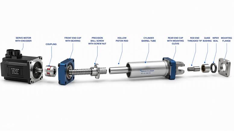
Figure 1. Exploded view of a servo electric cylinder: servo motor, coupling, end caps, ball screw, piston rod, barrel, seals, and mounting flange.
2.1 Servo Motor and Encoder
The servo motor is the power source of the electric actuator cylinder. It is usually a brushless AC servo motor with a rare-earth permanent-magnet rotor. Mounted on the rear of the motor, the encoder (incremental or absolute) feeds real-time position and speed signals back to the drive, closing the control loop. Motor flange size must match the cylinder’s rear interface exactly, or the coupling alignment will suffer.
2.2 Coupling
The coupling connects the motor shaft to the screw shaft. In an inline servo linear actuator, a zero-backlash jaw or bellows coupling is used; in a parallel (fold-back) configuration, a timing belt and pulleys replace it. The coupling must absorb slight misalignment while transmitting torque without lost motion.
2.3 Support Bearing Set
The screw shaft is supported by a matched bearing set — typically a pair of angular contact ball bearings installed back-to-back in the front bearing housing. These bearings carry the full axial thrust of the cylinder, so their preload directly determines the axial rigidity and repeatability of the finished electric lift cylinder.
2.4 Ball Screw
The ball screw is the heart of the actuator. Hardened, ground threads and recirculating steel balls convert rotary motion into linear motion with over 90% mechanical efficiency. Lead accuracy (commonly C5 or C7 grade) determines positioning precision. High-thrust models may use a planetary roller screw instead, which offers higher load capacity and longer life under shock loads.
2.5 Screw Nut and Piston Rod
The ball screw nut is bolted to the rear end of the hollow piston rod. When the screw rotates, the nut travels along it, pushing or pulling the rod. The piston rod itself is usually a chrome-plated hollow steel tube — hollow so the screw can retract inside it at the fully retracted position, which is why a servo electric cylinder stays so compact relative to its stroke.
2.6 Cylinder Barrel
The barrel is an extruded aluminum or honed steel tube that houses the screw, nut, and rod. It gives the cylinder its structural strength and provides precision bores at both ends for the end caps. T-slots or sensor grooves along the profile accept magnetic switches for position signaling.
2.7 Front and Rear End Caps
The rear end cap doubles as the motor adapter and bearing housing; the front end cap (rod end cap) carries the guide bushing and seal package. Both are sealed to the barrel with O-rings and clamped by tie bolts. Mounting features — clevis, trunnion, or flange — are machined directly into these caps.
2.8 Guide Bushing and Wiper Seal
A bronze or composite guide bushing supports the piston rod radially at the front cap, absorbing side loads. Behind it, a rod seal keeps grease inside, while the wiper seal scrapes dust and moisture off the rod on every retraction stroke. These small parts largely decide the service life of the whole servo linear actuator in dirty environments.
2.9 Anti-Rotation Mechanism
Because the nut must not spin with the screw, an anti-rotation device — an internal key-and-slot guide, a square extruded barrel, or an external guide rail — locks the rod assembly against rotation while allowing free axial movement.
2.10 Mounting Accessories and Rod End
The rod end carries a male or female thread for attaching the load, and accessories such as rod clevises, spherical bearings, and rear trunnion or flange mounts complete the installation interface of the electric actuator cylinder.
3. Step-by-Step Assembly Process
Assembly should take place on a clean, level bench with lint-free gloves, fresh lithium-based screw grease, a calibrated torque wrench, and bearing assembly sleeves. Follow the sequence below and never hammer any precision part directly.
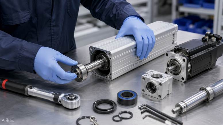
Figure 3. A technician inserting the ball screw assembly into the cylinder barrel during electric actuator cylinder assembly.
Step 1 — Inspect and Clean All Parts
Check every component against the bill of materials. Inspect the ball screw raceways for dents, verify the nut rotates smoothly by hand, and confirm bearing part numbers and preload class. Clean all machined surfaces with isopropyl alcohol and blow them dry with filtered air. Any burr left on an end-cap locating diameter will tilt the screw axis later.
Step 2 — Press the Bearings into the Rear End Cap
Warm the rear end cap to roughly 60–80 °C or chill the bearings, then press the angular contact bearing pair into the housing bore using a sleeve that loads only the bearing outer ring. Install the retaining ring or bearing cover and confirm the pair sits square with a dial indicator.
Step 3 — Install the Ball Screw Shaft
Slide the ball screw shaft through the bearings from the barrel side and secure it with the precision lock nut. Tighten to the specified torque, then stake the locking set screw. Rotate the shaft: it must turn freely with no notch points. This preload step sets the axial stiffness of the finished electric lift cylinder.
Step 4 — Pre-Assemble the Nut and Piston Rod
Bolt the ball screw nut flange to the rear of the hollow piston rod, using thread-locker on the fasteners. Attach the anti-rotation key to the nut body. Do not spin the nut off the screw during this operation — if the balls escape, the nut must be returned for reballing. Keep the nut protected with its shipping sleeve until Step 5.
Step 5 — Insert the Screw into the Barrel
Lay the barrel horizontally. Carefully transfer the nut from its sleeve onto the screw thread and push the whole screw-and-rod assembly into the barrel bore, feeding the rod through the front opening. Rotate the screw gently so the nut travels inward without forcing the anti-rotation key.
Step 6 — Clamp the Rear End Cap to the Barrel
Fit the O-ring onto the rear cap spigot, mate the cap with the barrel, and tighten the tie bolts in a diagonal cross pattern in two or three passes to the specified torque. Even clamping prevents barrel distortion and keeps the screw concentric with the bore.
Step 7 — Fit the Coupling and Servo Motor
Slide one coupling hub onto the screw shaft and the other onto the motor shaft, set the gap with feeler gauges, and tighten the clamping screws. Bolt the servo motor to the rear cap flange, then rotate the shaft by hand once more — the linear servo motor should spin the screw with uniform, silky resistance. Connect the encoder cable last, with power off.
Step 8 — Install the Guide Bushing, Seals, and Front Cap
Press the guide bushing into the front end cap, then install the rod seal and wiper seal into their grooves with a seal tool, lips facing the correct direction. Grease the bushing lightly, slide the front cap over the piston rod, and bolt it to the barrel. The rod should now slide in and out smoothly when the motor shaft is turned by hand.
Step 9 — Grease and Fit the Rod End
Inject the specified amount of screw grease through the lubrication port and stroke the rod fully several times to distribute it. Thread the rod-end fitting (clevis or spherical eye) onto the piston rod with thread-locker and lock it with the jam nut.
Step 10 — Final Test and Calibration
Power the drive, home the actuator against its reference, and run ten full strokes at low speed. Verify repeatability with a dial gauge (typical target: ±0.02 mm or better), check for abnormal noise and temperature rise, then run the rated load test. Record the results on the test certificate shipped with the electric actuator cylinder.
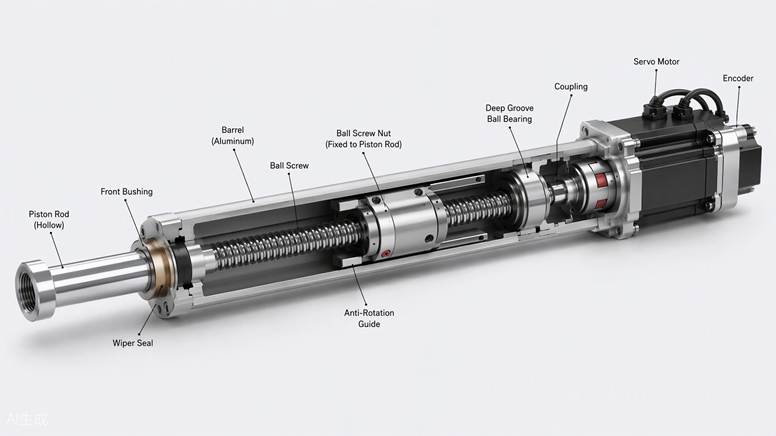
Figure 2. Cutaway cross-section of an assembled servo linear actuator showing the internal ball screw, nut, bearings, and anti-rotation guide.
4. Quality Inspection Checklist
Before delivery, every servo electric cylinder should pass four checks: (1) backlash and repeatability measured at the rod end; (2) thrust verification on a load cell against the force-speed curve; (3) IP-sealing inspection, with the wiper and rod seals visually confirmed after a water-spray or dust test when an IP65/IP66 rating is claimed; and (4) a noise and vibration run across the full speed range. Units that pass receive a traceable serial number engraved on the barrel.
5. Typical Applications
Large-format servo cylinders act as the electric lift cylinder in lifting platforms, press-fitting stations, and solar-tracker drives, replacing hydraulics entirely. Mid-size servo linear actuator models power pick-and-place gantries, filling machines, and test rigs. At the small end, the miniature rc linear servo actuator — essentially the same screw-driven architecture scaled down with an integrated control board — is the standard choice for RC aircraft retracts, robotics grippers, and animatronics, where a few grams and millimeter-level positioning matter more than thrust.
Conclusión
A servo electric cylinder is not mysterious once you see it as three cooperating subsystems: the linear servo motor and encoder for intelligent drive, the ball screw and nut for precise motion conversion, and the barrel, rod, guides, and seals for structural support and protection. Assembling it is a disciplined, sequential process — bearings first, screw next, rod and barrel afterward, motor last, then lubrication and calibration. Master these ten steps and the quality checks that follow, and you can build, audit, or maintain any electric actuator cylinder, from a heavy-duty electric lift cylinder on a factory floor to a palm-sized rc linear servo actuator in a robot — with complete confidence in the result.