
In modern precision automation, the linear actuator with step motor has become an indispensable electromechanical component. By integrating a hybrid stepper motor with a precision lead screw, the step motor linear actuator converts discrete rotational steps into highly accurate linear displacement. This article provides a comprehensive technical overview of structural design principles, critical performance parameters, product specifications, and real-world applications.
1. Structural Design Principles
A linear actuator with step motor is a compact device that unifies a stepper motor, lead screw, and nut into a single integrated unit. Its fundamental principle relies on the motor’s ability to rotate in precise angular increments—typically 1.8° or 0.9° per full step. This rotational motion is translated into linear displacement through the mechanical interaction between the lead screw and nut.
Core components include the stator assembly (electromagnetic coils), rotor assembly (permanent magnets), precision ball bearings, the lead screw, and the power nut. When electrical pulses are delivered via a stepper drive, the rotor advances step by step. Because the lead screw is coupled to the rotor, each step produces linear displacement determined by the screw’s thread lead and the motor’s step angle.
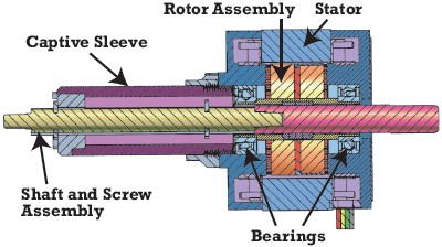
Figure 1: Cross-sectional view of a captive linear step motor actuator showing rotor assembly, stator, bearings, and captive sleeve.
1.1 Three Primary Configurations
Based on the lead screw and anti-rotation arrangement, step motor actuators are classified into three fundamental types:
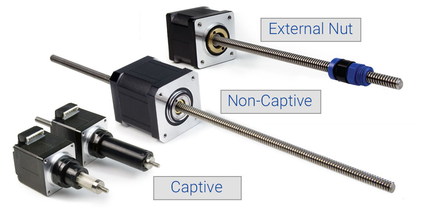
Figure 2: The three primary configurations—External Nut (top), Non-Captive (middle), and Captive (bottom).
Captive Linear Actuator: The lead screw extends and retracts while an integrated anti-rotation device—typically a splined shaft and captive sleeve—prevents rotation. Stroke is constrained by the motor body, making this ideal for short-stroke applications without external guidance. Common in precision metering pumps and proportional valve controls.
Non-Captive Linear Actuator: The lead screw passes through the motor and translates as the internal nut rotates with the rotor. The load must provide external anti-rotation. This configuration offers maximum stroke flexibility, as the screw can be manufactured in virtually any length.
External Linear Actuator: The lead screw rotates with the rotor while the nut is positioned externally. The load mounts to the nut, which translates along the screw. External actuators can use anti-backlash nuts for high repeatability and are common in positioning tables and pick-and-place systems.
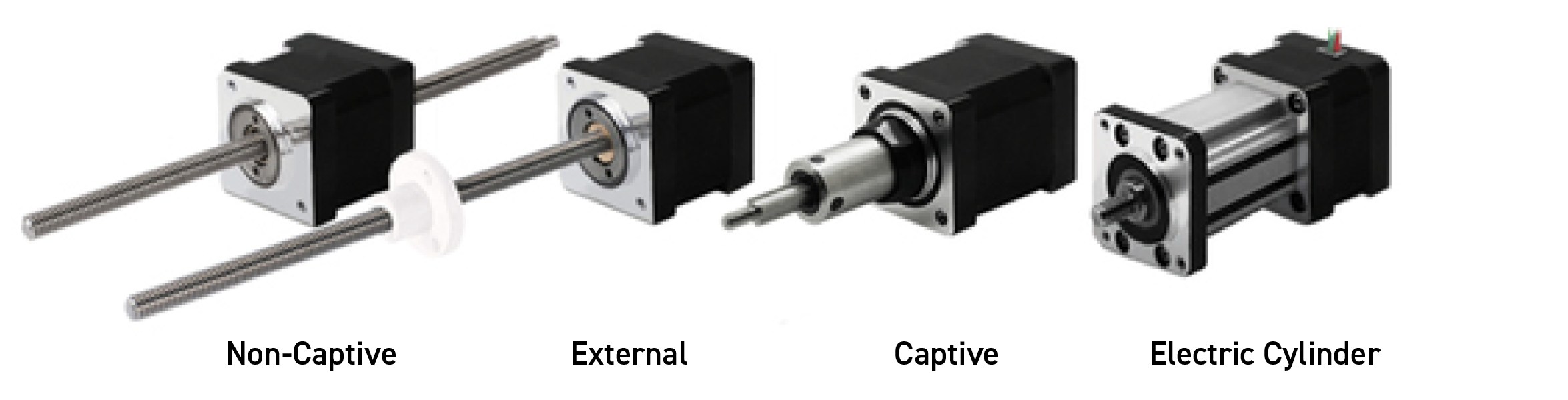
Figure 3: Product family showing Non-Captive, External, Captive, and Electric Cylinder configurations.
2. Critical Performance Parameters
Selecting the right step motor linear actuator requires evaluating these key parameters:
2.1 Linear Force and Thrust
Maximum force (in Newtons) depends on motor frame size, stack length, current, and screw lead. Larger NEMA sizes deliver higher thrust: NEMA 34 actuators can exceed 1,300 N, while compact NEMA 6 units deliver about 15 N. Force is inversely related to lead—a finer pitch generates higher force but lower speed.
2.2 Linear Speed
Velocity depends on pulse rate and thread lead. Higher leads permit greater speeds but reduce thrust and self-locking. Typical speeds range from a few mm/s for precision tasks to over 300 mm/s for rapid positioning. Manufacturers provide speed-force curves essential for proper selection.
2.3 Resolution and Accuracy
Resolution is calculated as:
plain
Resolution = Screw Lead ÷ Steps per RevolutionStandard 1.8° hybrid motors provide 200 steps/rev; with 1/64 microstepping, sub-micrometer resolution is achievable. Engineers must distinguish resolution (smallest step), accuracy (target deviation), and repeatability (position consistency). Anti-backlash nuts improve repeatability by eliminating axial play.
2.4 Screw Lead and Self-Locking
Standard leads range from 0.4 mm to 6.35 mm. Smaller leads increase force and self-locking (holding position without power), while larger leads favor speed. ACME threads offer robustness and self-locking; ball screws provide higher efficiency but may need a brake.
2.5 Stroke Length and Life Expectancy
Captive actuators typically offer strokes up to ~100 mm; non-captive designs accommodate much longer travel. Stepper motors have no brushes to wear out. Primary wear occurs in bearings and the screw/nut interface. With a safety factor of 2 or more and minimal side loading, quality actuators deliver over 20 million cycles.
2.6 Duty Cycle and Thermal Management
Stepper motors generate heat proportional to winding current. Overdriving can increase output by ~60% but requires duty cycles of 25% or less to prevent thermal damage. Proper heat sinking or reduced-current standby modes are essential for reliable operation.
3. Product Specifications and Size Classifications
Step motor linear actuators are manufactured across a broad spectrum of frame sizes:
| NEMA Size | Frame (mm) | Peak Force (N) | Max Speed (mm/s) | Resolution (μm/step) | Applications |
|---|---|---|---|---|---|
| NEMA 6 | 14 × 14 | 10 – 16 | 10 – 30 | 5 – 10 | Miniature valves, micro-dispensing |
| NEMA 11 | 28 × 28 | 30 – 80 | 20 – 60 | 2.5 – 12.5 | Medical pumps, optical stages |
| NEMA 14 | 35 × 35 | 80 – 150 | 40 – 100 | 2.5 – 12.5 | Lab automation, semiconductor |
| NEMA 17 | 43 × 43 | 150 – 350 | 50 – 150 | 1.25 – 12.5 | 3D printers, CNC, imaging |
| NEMA 23 | 57 × 57 | 300 – 700 | 80 – 250 | 2.5 – 25 | Industrial automation, testing |
| NEMA 34 | 86 × 86 | 600 – 1,300+ | 100 – 325 | 5 – 50 | Heavy positioning, robotics |
Double-stack variants provide 40–60% higher force in the same footprint. Guided modules integrate motors with linear rails and carriages for rigid motion over strokes from 50 mm to over 1,000 mm.
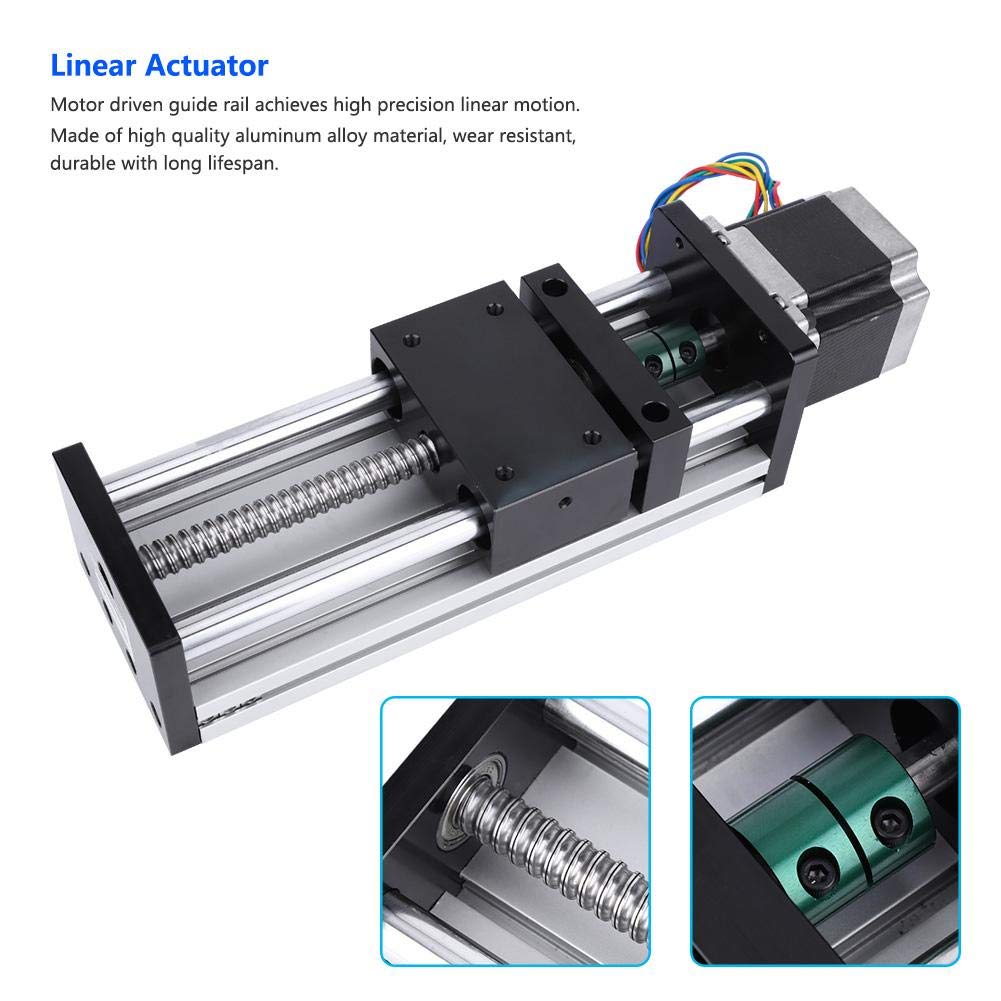
Figure 4: Integrated linear module with stepper motor, ball screw, and guide rail for automation.
4. Diverse Application Scenarios
The combination of open-loop precision, holding torque, and compact size makes step motor actuators suitable for a wide range of industries.
4.1 Medical and Diagnostic Equipment
Actuators drive infusion pumps, syringe pumps, and metering systems where accurate dispensing is critical. In blood analyzers and DNA sequencers, they position sample trays and pipetting heads with micron-level repeatability. Detent torque ensures positions are maintained during power interruptions.
4.2 Laboratory Automation
Liquid handling robots, chromatography autosamplers, mass spectrometry loaders, and microscopy stages all rely on step motor linear actuators. Open-loop operation without encoders reduces cost while maintaining sufficient accuracy for analytical procedures.
4.3 Semiconductor Manufacturing
Wafer stages, probe stations, and pick-and-place heads require clean, vibration-free motion. Brushless stepper operation eliminates particulate generation, and microstepping enables sub-micron positioning without complex servo feedback.
4.4 Industrial Automation and Packaging
Actuators control valves, adjust conveyor guides, operate dispensing nozzles, and actuate sorting gates. Deterministic step motion integrates easily with PLCs. In packaging, they handle product placement, labeling, and carton erecting at high cycle rates.
4.5 Imaging and HVAC Systems
CT scanners and MRI machines use actuators for focal adjustment and filter positioning. Quiet microstepping is ideal for patient-facing equipment. In HVAC systems, compact captive actuators control dampers and valves efficiently, holding position without continuous power.
5. Drive Electronics and Control
Step motor actuators require compatible drives:
- L/R Drives: Simple and cost-effective for low-speed or battery-powered applications.
- Chopper Drives: Industry standard, delivering superior torque at speed via current regulation.
- Microstepping Drives: Subdivide steps (up to 1/64), reducing vibration and noise while increasing resolution.
- Closed-Loop Drives: Encoder feedback detects missed steps, combining stepper simplicity with servo reliability.
6. Conclusion
The step motor linear actuator bridges the gap between simple solenoids and complex servo systems. Understanding captive, non-captive, and external configurations enables engineers to select the optimal form factor. Attention to force, speed, resolution, lead, and life expectancy ensures reliable performance over millions of cycles. From medical pumps to heavy-duty industrial positioning, the linear actuator with step motor remains a precise, cost-effective, and compact motion solution.